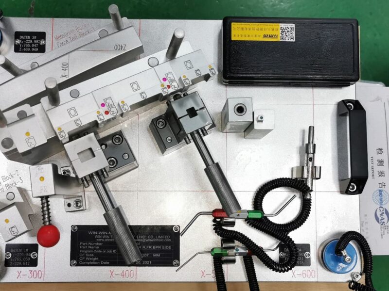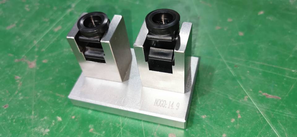
Design requirements for checking fixtures
1 The design of checking fixtures is based on CATIA, product drawings, DTS smell paper, GD&T information, MCP drawings, etc. and this agreement. The checking fixtures are required to be accurate in positioning, free in movement, and easy to operate.
2 The checking fixture body shall not exceed the base of the inspection area at any moving position. The design of the checking fixture shall ensure the convenience and safety of parts taking and placing, prevent scratching the checking fixture, and add 2mm gasket for protection if necessary.
3 The design proposal of the checking fixture shall be able to reflect the overall structure of the checking fixture and each part, including the disordered positioning of various car body components, the number and position of the positioning surface, the number of pressing points, the fv. convoluted pressing method, etc., and determine the detection method and detection requirements of each part, and explain them with a simple sectional drawing. The scheme shall be countersigned in the form of 3D digital model of checking fixture combined with 2D drawing plate.
4 Design requirements for hole location detection: when the hole is detected with a cylindrical pin, the diameter of the detected part of the pin is designed and manufactured according to the diameter of the hole to be detected minus 0.8mm; when the hole is detected with a scoring pin, the JtiJ wire sample is n! The diameter of i is hole diameter D+4. When the elliptical hole is detected with a cylindrical pin or a marking pin, the detected part is the minor diameter of the elliptical hole (the waist hole detection method is the same as the elliptical hole).
5 All pins, pin sleeves, and positioning surfaces and structures must be designed according to the three housing standards (or the three housing standard parts can be purchased directly).
6 Fixture positioning datum and chess and fixture positioning datum system: the fixture clamping point shall be consistent with the fixture clamping point as far as possible.
7 It must be ensured that under normal use frequency and good maintenance, the checking fixture and its corresponding drawing die and welding clamp have the same service life.
Drawing requirements
- The design drawing of the checking fixtureis usually 1:1 1: 2, 1: 3. The basic requirements are to clearly express all structures, dimensions and relevant technical requirements.
2 The first sheet of the design drawing is the specification of the checking fixture. The description table includes information such as part status, checking fixture status, materials, detailed list, version number and change record.
3 The checking fixture drawing can completely reflect the overall structure of the checking fixture and the specific structure, performance and design dimensions of each part. All drawings provided with countersignature must be formal, have been checked, reviewed and approved, and can accurately mark the size, performance and heat treatment method. The checking fixture drawing must be drawn with three views (and the reference line of the vehicle body must be marked), and strictly refer to the checking fixture drawing provided by Party A.
4 General assembly drawing: referred to as general drawing, including:
Graphic part: plan, sectional view, partial detailed drawing, etc. representing the shape of the checking fixture

Schedule:
- a) Indicate the checking fixturenumber, product name, product number and user name:
- b) Material, quantity, heat treatment, standard number, etc. of each component and structure of the checking fixture:
- c) Operation instructions of checking fixtures, etc.
Technical requirements:
- a) The design basis of the checking fixtureis the three-dimensional mathematical model (CATIA) of the product, product drawings, DTS drawings, GD&T information, and MCP drawings:
- b) Manufacturing standards and special requirements of checking fixtures:
- c) Color requirements for checking fixtures;
- d) Indicate the page number of each drawing and product drawing.
5 Product drawing: The drawing of the checking fixture shall be provided with a product drawing, and the coordinate grid lines and coordinate values shall be drawn, and the hole diameter shall be marked. Whether it is a product drawing or a product status document drawing, the product name, product number, material, material thickness, digital plane position and material thickness direction shall be indicated.
6 The final design drawing shall include the operation, maintenance guidance and operation sequence for using this kind of checking fixture, which shall be in both Chinese and English
7 The detection block at the contour corner, the feature line of the matching part, and the sudden change of the surface shall not be broken.
8 Within one month after the signing of the technical agreement, Party B shall provide the checking fixture rework and repair operation procedures, which shall be approved by Party A.
9 Color specification of checking fixtures:
Positioning surface and supporting surface 1mm
Measuring surface of scoring hole 2mm (1mm)
Detection surface 5mm (3mm)
Flatness detection surface 0mm
Inspection surface of visual hole 8mm (6mm)
Vertical gauge to pipe end surface 8mm (6mm)
Non inspection surface area, frame and support:
10 Label identification information (updated when necessary): year type, production year, manufacturer name, tested part name, tested part number, benchmark coordinate value of gauge number, total weight of gauge, manufacturing date and last modification date The label is riveted on the gauge with 1mm aluminum plate
