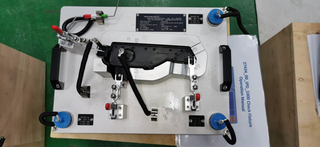
Different classification methods of automobile checking fixtures
The automobile checking fixture is a special inspection equipment customized according to the requirements of the demander. It can not only inspect the shape, thread trimming, fold line and surface position of the parts, but also detect the relative position of the hole position.
Material of body:
1 Resin checking fixtures; (5166/Weishi 460)
2 Aluminum checking fixtures; (Cast aluminum ZL107/duralumin LY12)
3 Iron checking fixtures; (cast iron HT250/steel 45)
4 Wooden checking fixtures; (Hardwood)
5 Other categories (such as glass fiber reinforced plastics, honeycomb panels, etc.)
Different styles:
1 Japanese and Korean checking fixtures: Honda, Toyota and Nissan have different checking fixture standards, which are more practical and reflect the loading effect!
2 European and American checking fixtures: based on universal checking fixtures, they are highly theoretical, generally in free state, and have high requirements for parts!

Function of the checking fixture:
1 Single piece checking fixture (single item checking fixture, semi-finished product checking fixture in the process, process checking fixture, CHECKING FIXTURE, referred to as C/F): mainly used to inspect single parts. Parts checking fixtures are mainly used to complete the measurement in the process of product processing. It is often necessary to detect the surface and emphasize the continuity of the surface.
2. UNIT GAUGE (UG for short): refers to the inspection measuring tool used after the assembly of body parts, usually more than two parts. The assembly checking fixture is mainly used to inspect the mutual position and matching relationship of sub assemblies and the matching accuracy after assembly.
3 Opening checking fixture: OCF is the abbreviation of Open check fixture in English, which is translated into Chinese as opening checking fixture. Common checking fixtures are used to inspect products; On the other hand, the OCF checking fixture is used to simulate the product parts in reverse to detect the peripheral parts of the product. It is used to simulate the loading positioning point of the product, and simulate the shape of the matching relationship between the product and the peripheral parts. It is used to imitate a similar product standard sample to detect the matching state of its peripheral parts during loading. Therefore, OCF checking fixture is also called “sample piece” or “sample frame”. Or OPEN GAUGE (OG for short), which is used to inspect the relevant shape of the opening after body welding, such as the front windshield opening gauge.
Product types:
1 Stamping parts checking fixture;
2 checking fixtures for injection molded parts;
3 checking fixtures for machined parts;
4 checking fixtures for body trim and covering parts;
5 Glass checking fixtures.
Features of positioning mode and detection evaluation:
1. Holding Fixture: It is used to position and fix the product in the way specified in the product drawing. It has no detection function and is a special fixture for CMM measurement. As an auxiliary support when measuring parts with CMM, the measuring support must be milled according to the CAD data of the parts. The measuring support of some special parts should also have the function of some checking fixtures.
2 Checking fixture: locate and fix the product in the way specified in the product drawing, establish the offset surface and flush surface of the product itself, establish the offset line of the feature line on the product itself, establish the sleeve or pin corresponding to the feature pin or hole of the product itself, and evaluate the deviation between the actual product and the ideal product (digital analog).
3 Cubing fixture: locate and fix the product according to the actual loading or assembly mode, establish the ideal matching surface of the product’s opponent (environment) product, and evaluate the matching deviation between the actual product and the ideal matching product (data) of the opponent (environment).
4 Mold: It is mainly based on cavity surface or shape positioning. The orientation system is not necessarily reliable. The theoretical product boundary and/or line are established to evaluate the deviation between the actual product peripheral shape and hole position and the ideal product digital model.
